

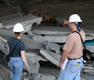


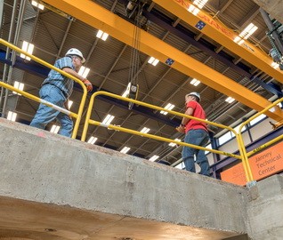







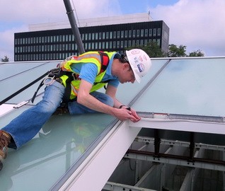




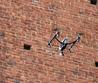












Structural load testing is an important tool for evaluating existing buildings and building components when traditional analysis alone cannot confidently resolve questions of strength, serviceability, or code compliance. These situations commonly arise in aging structures, adaptive reuse projects, historic buildings, and facilities with incomplete documentation or nontraditional construction. While load testing can be highly effective, determining when it is appropriate, how it should be conducted, and how results should be interpreted require careful engineering judgment.
In this webinar, engineers John Pearson and Rich Lindenberg provide a practical overview of structural load testing for existing structures. The presentation discusses why load testing is performed; how it is addressed in building codes and material standards; and the differences between proof, ultimate, and failure testing. Through a series of real-world case studies, the presentation illustrates how load testing can be used to manage uncertainty, validate analytical assumptions, and avoid unnecessary repairs or strengthening.
By the end of the webinar, you will be able to:
- Identify common scenarios in which structural load testing is an effective evaluation tool and when alternative solutions may be more suitable
- Explain the code basis and performance objectives for different types of load tests
- Distinguish between load-controlled and displacement-controlled testing approaches
- Describe how load testing can be integrated into broader structural assessment and risk management strategies
Attendees are eligible for one American Institute of Architects (AIA) HSW Learning Unit.
more to learn
View this webinar in our interactive audience console to earn 1 AIA HSW learning unit, access related resources, submit questions to the presenters, and download a certificate of completion.
John E. Pearson, Principal and Laboratory Manager
Liz Pimper
Hello and welcome to today's WJE webinar, Structural Load Testing: When Calculations Aren't Enough. My name is Liz Pimper and I'll be your moderator. During the next hour, engineers John Pearson and Rich Lindenberg will provide a practical overview of structural load testing for existing structures. This presentation will discuss why load testing is performed, how it is addressed in building codes and material standards, and the differences between proof, ultimate and failure testing. This presentation is copyrighted by Wiss Janney Elstner Associates. And now I will turn it over to Rich to get us started. Rich.
Richard Lindenberg
Thank you, Liz. We have a great mix in the room today. Engineers, contractors, DOT officials, whether you're evaluating an existing structure, dealing with a construction situation where something isn't right, dealing with a bridge load rating question. We think there's something in today's presentation for you. Onto the learning objectives, I'll call out the fourth bullet explicitly integration into the broader assessment strategy since it's one of our most relevant to decision makers and owners. And this is going to set up the case study payoffs. So integrating testing is really the theme that ties all these ideas together. And hopefully by the end, you should be able to answer the question, when do you pick up the phone and call for a load test?
So we'll be covering three things, why load testing matters, when is the right tool, and real world case studies. So let's go. Load testing isn't just a niche specialty of WJE. It's literally how the firm started. Jack Janney's early work was predicated on the idea that when calculations run out of answers, you ask the structure directly. Field testing is a core element of asking the structure. You can see another photo here on the right. The Trestle, capital T, an enormous structure built to study the effects of electromagnetic fields from a nuclear blast made entirely from the wood to support the 747 during testing. To do that load test, we use large dump trucks, which are quite small in this photo. You can see them in yellow. Those are the ones with the tires larger than a person. What that history gives us is a perspective that most firms don't have.
We've done a lot of load tests with significant responsibilities that require engineering understanding. This is for government clients, transit authorities and school districts. We have seen what happens when the load tests are done well and what happens when they're not. The lessons are baked into how we approach our projects.
We've been doing that ever since and in the field and in the lab. That history is why we can speak with some confidence today. Load testing is just a tool and is an integral part of our analysis work. And we don't just test to test. It's about developing the right tests, develop right solutions. So why do we test? At the highest level, we do it when calculations alone can't give us the answers. The first category is structural uncertainty. No drawings and no materials, hidden deterioration. The second is when load limits are conservative and there's a real opportunity to demonstrate better performance than calculations suggest, especially for bridges or posting might be on the table. For bridge owners and DOTs in particular, load testing can be the difference between maintaining full capacity and posting a reduced load. Posting isn't just inconvenient. It's rerouting trucks. Hurts commerce can cost millions in detours or alternate routes annually.
But load testing lets us challenge conservative assumptions with real data.
For building owners and facades, we can demonstrate safety to satisfy authorities having jurisdiction, providing adequacy before it becomes a liability. When we're doing rehab work or a change of use, load testing fills the gap between the old drawings, say what the structure needs to do today. Or maybe contractors when you come up with the issues of construction, an existing structure within an unknown condition gets exposed. Can it carry the loads? A load test can answer that question in many cases before a problem becomes a claim. And for building engineers doing adaptive reuse, we have heard the question, can the 1900s clay tile arch floor handle loads for this new use case? A load test can give you a defensible answer. And for those of you building finite element models, you know that the models are simplifications. Load testing can help provide ground truth. We can get real distribution, real load pass, and we can update the system updating those models with confidence.
In some projects, there's no guidance at all. And in those cases, load testing is how we write the criteria ourselves. Okay, so before we get into case studies and I want to anchor this to codes that many of you work with every day. Load testing isn't something that WJE invented. It's built into the legal framework. IBC has an explicit pathway. If you can demonstrate structural adequacy through a load test, the cod accepts that as an equivalent to a calculation-based design. The guidance therein, that's a powerful tool. AASHTO provides the same pathway for bridges. Guidance therein provides both proof and diagnostic testing. Let me draw a quick distinction that will come up in the case studies. Proof test is essentially closer to a simple pass/fail. We load to a target level and we either meeting a metric or it doesn't, which case we might have to post the bridge for that lower metric.
A diagnostic test is about measurement. We apply known loads and measure how the structure responds. Then use that data to update our analysis. Both are legitimate and the right choice depends on the question you're trying to answer. Both types of testing are important tools enabling DOTs and maintaining load ratings and avoiding postings or limiting permit loads.
There's actually more codes and standards. To name a few for concrete structures which have the most complexity ACI 318, 437 and 562 form a connected chain that points directly to load testing methodology. Experienced WJE staff participate in these committees. For steel, AISC gives explicit guidance on load application and acceptance criteria. ASTM provides even more details. The takeaway, whatever material you're working with, there is recognized guidance typically, code-sanctioned pathways to load testing. We're not operating out of the box. You practically need a load testing expert just to navigate the bureaucracy in some cases. So practically speaking, regarding all this guidance, what this means is if you bring a load test result to a building official, a state DOT or an owner's representative, you have a documented basis to point to. It's not a workaround. It's not an exception. It's a recognized engineering approach. That is important for you when you're in a room with a skeptic or regulator.
Lastly, I'll note for existing buildings a set of circumstances where we can advise load testing is not required. And in some cases we get this question. Under the international existing building code, you are not required to prove by calculation or load testing the performance of a structure. You just need to accept three provisions. You're not increasing the load demands. So in short, you're maintaining the historical use load speres. Two, you're not performing alterations that would reduce the capacity of the elements you're considering. And three, in review of the structure, there's not distress indicators that would cause concern for the capacity you're reviewing, such as cracking around a column or significant floor deflection. In short, you can continue to use the structure as it's always been used. These have come up regularly. Various adaptive reuse historic projects. Client buys a 1940s building and wants to convert it to an office lobby.
The structural system's intact. You're not adding mechanical equipment that adds significant loads and there's not visible distress. In that scenario, IEBC is you do not need to do a load test and you don't need to demonstrate that through calculation. You're just reusing the structure. So that's a cost and a schedule benefit worth knowing and we wanted to pass it along. Where load testing becomes relevant is when one of those three conditions for buildings is not met. And that's where our assessment process starts.
John Pearson
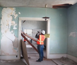
All right. Thanks, Rich. I'll go over here. Codes tell us we can load test. That doesn't mean we always should. The question is when is load testing actually the right tool? First rule is probably obvious once you say it out loud. If a structure is clearly deficient, don't load test it. Strengthen it or replace it. Load testing a structure you already know is failing, is dangerous and tells you nothing useful. Here's an example of an existing building that has been sitting vacant and exposed to the elements purchased with the intent to develop multi-unit housing. The new owner wanted to load test it to find out if it could support code loads.
Examination and condition assessment and samples taken told us this building definitely was not a good candidate for load testing. By not doing a load test, we are saving money and time that can be used to design repairs or replace the structure. The second example, this time load testing was considered, but analysis came first. During construction of a new building, missing or misplaced rebar were reported and the owner and the structural engineer were considering a load test. We suggested identifying the areas of concern using destructive methods, calculating capacity with what's actually there before performing a load test.
We found some locations marginally deficient by code, but not grossly deficient. We ran the analysis with the reinforcement placement as built, not as designed. Several zones were marginally short of code requirements, but not catastrophically deficient. The gap was small enough that supplemental reinforcement could be added efficiently and targeted only to those locations. The load test was never needed and the owner avoided both the cost of a test and the time of loading a structure. They already knew where deficiencies existed and these were addressed. The lesson analysis first then if and where analysis still leaves uncertainty, perform a load test.
In that narrow zone of clearly deficient and clearly sufficient where a load test adds value. Proper load testing can confirm that real behavior exceeds what the calculations conservatively predict. Load testing comes in all shapes and sizes as you will see as we go through the case studies. It should be apparent and is implied as we go through some case studies that before doing a load test, there are certain things that need to be considered. These include safety and performance such as anticipating what could happen if the performance is not as expected so people and surroundings are safe in applying the load in a manner that is easily removed should there be a concern about performance. Those come immediately to mind. With that, I now give it back to Rich to continue with our load test case studies.
Richard Lindenberg
Thanks John. So we have eight case studies spanning bridges, buildings, facades, life safety components and transit system. They deliberately cover the different areas and structure types, pest types, and the reasons that we talked about. So the big goal is to leave you with enough examples that when you see a situation in your work, something in today's presentation hopefully connects. If you're a DOT engineer, bridge examples, contractors, building and component examples hopefully resonate. And for everyone in the room, the SEPTA case study at the end shows how a full investigation and repair cycle can be built around a series of low tests.
We'll follow a simple format. Here's the problem. Here's what we did. Here's the value that it delivered. First up, GSA head building in Washington DC. A 1960s precast structure. Granite stone cladding at the end stairwells and the connections were failing. These stone panels weighing in some cases over a thousand pounds are held onto the building with four or more connections as you would expect near the corners of the rectangular panel. Problem is over the years that some of these connections were failing and emergency anchorages had to be installed to secure the panels for safety. So what was going on?
Well, the kerf anchorages, you can see an example of kerf anchorage on the left where the kerf is too shallow to support the calculated demands. Kerf is essentially a narrow slot cut into the back top of the stone side. In this case it's about three inches wide, typically two to three inches deep. And a stainless steel disc or hook clip is inserted as in that slot that anchors the panel back to the building behind it. This is how panels stay on the building if you have heavy winds. If the kerf is too shallow or too close to the edge of the stone, that clip that doesn't have enough material to pull against. By observation from the failed connections, this was the real issue. And this is what kind of drove the need to have a project that re-cladded the building. So removing and actually replacing.
And we could see by calculation many of those connections were inadequate in the beginning phases of the project. And when we basically disassembled the cladding, we could see many of these issues permeate through. So we needed to determine which ones would actually require repair and which ones we could keep. The calculations are based on assumed limited material properties. This was a historic structure. And regarding those material properties, the granite quarry that these stone panels had come from had been closed for decades. So there was no material that we could test to develop the standard type of engineering material information that we would use. So we had to use more lower bound numbers for the support of that.
And we wanted to avoid changing out the appearance as well as the economics of purchasing new stone to reclad the building. So the path forward was to find a way to verify connections that were adequate and not just by calculation, but by proof. On the right, you can see a test setup. We have a simple frame to support the panel, a small hydraulic ram capable of over a thousand pounds of force, calculated the design load, factoring in wind, material safety and safety margins, and then built a straightforward decision tree, whether like John had said, clearly deficient, clearly okay, or somewhere in between, which is when we needed it to test. If yes, no repair would be required.
So we had to develop a system to make those decisions. The test setup was a lateral pull on each of the curves. It required that design load. Most of the connections required about 500 pounds to meet the design. We're simply applying that lateral load against the frame again to resist on the panel. So over a thousand connections were actually tested. The result in this case, all passed and all could be reused. Repairs were required only where we were finding clearly deficiency. And fortunately we didn't have any tests that failed. Not everywhere do the calculations require or demonstrate inadequacy. And so those connections were fine to move forward. That's the load test delivering a value, avoiding over repair, reserving appearance, satisfying the authority, having jurisdiction, the government in this case. So to put that in perspective, if the test program had not existed, the conservative approach would've been to repair every connection that failed by calculation over a thousand which was a significant fraction of the panels and their connectors.
So reinforcing repairing connections all represents a significant amount of effort, hours of labor. So this is a significant cost and schedule savings.
The load test program essentially converted a worst case scenario into a targeted program that could be completed in less than half an hour. Connections that passed, stayed, connections that failed, got retrofitted. The building kept its original stone. The government kept its historic facade and the project team had to document a code compliant proof for every connection on the building. Our next example is a different world entirely. A precast bridge girder for the Louisiana DOTD and a problem that starts in transit before the girder even reaches the job site. Here's the problem. A long span precast girder leaves the fabrication yard and by the time it arrives on a job site, there's a crack in the top flange. Why? Because the bridge deck, the girder's top flange is intentioned during transport during occasions. The dead load was designed for isn't there yet. Cracking at this stage becomes a life of bridge maintenance issue.
Louisiana DOTD knew that and wanted to know what loads does the girder actually experience during a multi-hour road trip to develop better criteria and specifications.
So just to clarify, this prestress concrete girder of this length is specifically designed to carry a very large compressive force in the bottom. That prestress is what gives it the strength to span the bridge and carry the loads such that once of all the loads are on, it balances out. The problem is in transport without the bridge deck to distribute the load and without the dead weight it was designed for, the flange can actually go into tension. And that's a condition that concrete doesn't handle very well poorly. And these are girders sometimes traveling hundreds of miles on the back of transport trucks, not always on highways, going over railroad crossings, navigating curves, and every bump can be a loading event.
What we did was instrument the girder during transport. In real time, we captured video of where the girder was on the road, synchronized that with strain data displayed as color maps. You can literally watch the stress distribution in the bottom left-hand corner change as the truck navigates a curve. From that we characterized the full transport envelope over the whole driving distance. Louisiana DOT now had a real set of data to better understand how the girders could be safely transported to site and apply appropriate safety factors for the formation of design criteria and specifications. The last point is really worth sitting on. Before the test program, the design guidance for transporting long-span prestress girders was largely based on injuring judgment, rule of thumb, and conservative assumptions. The test generated real data that can inform DOT specifications and fabricator practices moving forward. So load test functioning not just as a project tool, but as a research and standards development function.
So it illustrates the targeted diagnostic program that can identify what is actually happening and give you basis for addressing it.
Continuing down the highway for our bridge audience, DOT engineers and bridge owners. We'll highlight a couple more bridge examples before handing it back to John. Many of us have seen bridge postings. DOTs have significant concerns about that along with permitted loads. Here's an example that addresses where a conservative calculated load rating can be improved. The Cedar Street Historic Bridge is a historic truss bridge in Peoria, Illinois. Built in originally in 1932 carrying four lanes of traffic across the Illinois River consists of multi-span types including deck trusses and cantilever trusses with hundreds of gusset plate connections that are critical to the structural performance. As the bridge has aged, the loading demands increased. Concerns arose about how traffic loads were actually distributed through this complex set of truss elements, making an ideal candidate for load testing to better understand the true behavior. So there was a concern that the bridge might require a posting due to calculated road load rating.
We instrumented truss members framing into critical gust plates with strain gauges then ran controlled truck load tests in multiple lane configurations and collected a week's worth of load in - service traffic data. Field measurements show that real distribution often differed from code assumptions allowing refinement of distribution factors and a more realistic member forces. In key areas, load effects were lower than assumed supporting improved load rating capacity without physical strengthening. By replacing conservative assumptions and measured behavior, load testing unlocked existing capacity in the bridge. So let me translate. Improved load rating means in practice for a DOT, a bridge with permit restrictions or postings is a bridge that heavy trucks are limited. Detours and alternate routes mean added costs for every freight ship using an alternate route, wear on alternate roads and economic impacts for communities in the state that depend on those routes. An improved load rating can remove postings or prevent the need for it ever to be issued without a single repair.
And one more stop on our road taking an idea of handling complex fatigue related issues. Now in Dallas IH 345 is a miles long elevated structure in the downtown area that carries significant truck and commuter traffic through the downtown zone. It was built in the 1970s and like structures of that era used a connection detail that was not well understood for its fatigue behavior at the time. By the time that WJE was engaged, the scale of the problem was already extensive. Individual cracks across many connections spread over miles of the structure and full replacement or is not even in the feasible for timeline or budget. Authority needed to have a strategy. What do we do? What do we focus? Where do we focus? And how do we know what retrofit works? And we make a difference. Load testing was a part of that strategy. Thousands of fatigue-sensitive details, thousands of cracks already documented.
So you need to understand how these issues relate and how we can come up and retrofit intelligently to extend service life.
We had both global behavior and detail connection zone test programs. For the global behavior, strain gauges on the top flange, web, bottom flange. Then we ran trucks of known weights across those spans in different lane configurations. That data went straight back to the finite element modeling team and those models could be updated with real distribution factors, not assumed ones. The modeling teams could then identify locations along the roadway where anticipated fatigue related issues would be greatest. And that could be prioritized or list of retrofit designs. So load testing turned a thousand cracks problem into a targeted solvable one. You can see part of the results side, the imagery of the load test trucks. The image below that is an instrumentation snippet layout. This is a reminder that load tests take time and often have their own set of drawings for a reasonably sized program. And to the right is the global behavior of the two by two configuration, which is actually the picture we saw it on the slide prior.
Very clean and clear loads we measured in the field. What we gave the DOT was documented confidence, not just in the retrofit design, but in decision to extend structured service life.
John Pearson
All right. Thanks Rich. Load testing is often required by code or by the authority having jurisdiction to formally demonstrate that a structure or component meets its intended service safety requirements. Demonstrate that with a load test of suspended scaffolding. Now if you are a building owner or a facilities manager responsible for a high rise, this is not an abstract scenario. OSHA requires that suspended scaffolding anchor points be proof tested after installation and before being put into use and after any modification. Many building owners don't realize that the company that installed it said it's fine is not sufficient documentation. The OSHA requirement specific four times rated capacity applied in the direction of actual use with a qualified person overseeing the test. The part of direction of use in applied load is where tests can and do go wrong. The issue is building owners need to demonstrate that suspended scaffolding supports meet OSHA requirements.
They need to have documentation for users that the suspended scaffold supports have been load tested and passed the OSHA requirements. A proof load test is ideal for this.
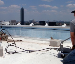
And bases need to be proof loaded before placed into service and following any major alteration to an existing installation to demonstrate compliance with OSHA requirements. It is also smart to load test when there is concern about the condition of the Davit base to the building connection. It is commonly known that roofing systems can seal the Davit base connection and if there are leaks, deterioration of the connection will be hidden. Without removing the roofing system and examining every Davit base, load testing is a direct way to evaluate the required performance. The OSHA requirements are specific. This means Davit bases and arms or outriggers must be proof load tested to four times the rated capacity, not just the rated load, to account for the possibility of an overload such as an ascending swing stage hooking onto an obstruction or portion of the facade causing a load on the supports that exceeds the rated capacity, just as an example.
Here's what a correct Davit arm and base test looks like. For the arm, we fasten the arm based to a structural anchor in the laboratory floor, apply load using a lever hoist to the actual direction of use, the direction that creates the critical bending moment and load it to four times the rated capacity. Calibrated load cell in line is used to measure and record the applied load. Displacement of the Davit arm is measured using calibrated transducer. When we release the load, we measure whether the arm returns to its starting position. Some may ask why take a Davit arm off the building and test it in a laboratory? Well, in order to test in the direction of use on the building would require connecting the Davit arm to the Davit base and loading over the side of the building. If there is a failure, the Davit arm could go over the side if not properly secured for such an occurrence.
It is safer to perform the test in a controlled setting. Similarly, for the Davit base on the building, we apply the load to four times the rated capacity using a hydraulic ram to the base through a cantilevered beam in the direction of use to create the bending moment and measure displacement. If the Davit base doesn't return to its starting position, something has permanently deformed and we need to investigate further. Pass means pass when loaded correctly.
Here's an example of a load test that was performed by others, but by only checking the rated capacity. And the load was applied in the wrong direction, not the direction the base would actually experience in service. Load was applied to the Davit base in the upward direction and a bending moment was not applied. The Davit base passed that test, then it failed in use. That's not an argument against load testing. It's an argument for doing load testing correctly. A load test was on record. A certificate of compliance existed, but the test had been performed incorrectly. Wrong load, wrong direction. And so the certificate was meaningless. This is an important practical takeaway here for anyone in this room whoever reviews a load test certificate or approves a load testing program. A load test result is only as credible as the methodology. Checking the box is not the same as performing a test correctly.
This is why it is very important, especially when lives are directly dependent on the structural system. A designing test means we know what to test, at what load, in what direction and why.
It's another example of a load test that required repairs or strengthening of a wood roof truss. So an elementary school with damaged wood trusses supporting the gymnasium roof. The issue was the gymnasium roof had experienced a load that exceeded the design load and had splits in its members. This one I believe we can all relate to. A grade school gymnasium roof supported by six wood trusses. Think about what that means in practice. Damage is noticed during the school year. The gymnasium is where kids eat lunch, have PE class and where concerts and other activities are scheduled. An engineer comes out, looks at these trusses, finds splits and cracks in all six of them, and the call is made. Shut it down. Now the school district is facing a choice. The first option they heard was remove and replace all six trusses. That is a major construction project.
That means a gymnasium is closed for months, not weeks, disruption to the rest of the school year, costing hundreds of thousands of dollars and a conversion and a conversation, sorry, with parents about the disruption and how activities will be canceled or inconvenienced. The second option, the one the school asked about was, is there an alternative? That is when they called us.
Condition survey of all the trusses was performed to understand the extent of damage and to all of the trusses. This is information we repaired a design or we designed a repair and the repair concept involves stitching fractured timbers with lag bolts and extending the bottom cord shoe plate. But before they could resume using the gym without safety concerns, there was a need to prove the repair works. That's where the load test comes in. With one truss repaired, a load test was performed. And this is one of the more elegant aspects of field load testing for roof structures. Water can be used as the applied load. We set up commercially available swimming pools, the kind you might see in backyard on the roof along the span of the repaired truck. We filled them with a known volume of water, which gives us a known evenly distributed load.
The load builds slowly as water fills so we can stop at any point if something unexpected is happening. We watch instruments in real time and when the test is done, we drain the pool. There's no heavy rigging, no crane, no complicated test apparatus, water pools and a calibrated measurement system. When the water was drained, the structure returned to its pretest position. The repair truss sections were examined and no distress was found. The repairs performed as designed. The remaining trusses were repaired. Major disruption in the school year was avoided and school officials had confidence that the roof would be able to support design loads. The school year finished on schedule. The trusses are still there, repaired and load tested serving students today. The total disruption was measured in days, not months, and the repair costs a fraction of full truss replacement. That what a well-designed load test program delivers, not just a technical answer, but a path forward.
The next example, a museum renovation and a question about whether new heavier light fixtures could be safely supported by connections with no drawings and no history of the connection. You might notice there's a recurring theme across these case studies that I want to state explicitly. Load testing generates documentation. This next example highlights this. The museum wanted to upgrade their lighting although the lighting was going to be with heavier fixtures throughout. The connection between the new fixtures and the concrete deck ran through an electrical box embedded in the concrete and there were no details of the connection to use for analysis.
No drawings, no record of how it was connected. And the museum was very risk adverse and did not want fixtures potentially falling onto the collection or any museum visitors. A load test was the only way to get confidence. The design load was determined based on the weight of the new lighting system. Load was applied through the lighting track through the connector and loaded to the required factor design value. The CMU blocks used provided a simple dead load-based test load. Every connection in the museum was tested individually. They all performed. The museum had documented proof of every fixture and gave them confidence in the system. The museum now has a test record for every single light fixture connection in that space. If fixture ever fails through improper installation or of new equipment, through an accident, through anything. They have a record that at the time of renovation, every connection was proof tested and found adequate.
The documentation protects the museum legally, satisfies their insurer and gives their facility staff a baseline. For building owners, contractors and engineers in the audience, that documentation function of load testing is often a valuable as the structural analysis or structure itself.
This next example is about lateral displacement performance. This is a seismic zone application and it's a good illustration that load testing isn't always about loads. Sometimes it's about proving displacement capacity. This is a good moment to address one of our learning objectives directly. The difference between load control and displacement controlled testing. Every test we have discussed so far has been load controlled. We apply a specific force, measure the structural response. That is the appropriate approach when the question is, can the structure carry a specific load? But sometimes the question is different. In a seismic region, critical design question for a facade panel is not how much a vertical load can it carry. It is will this panel stay attached when the building sways several inches during an earthquake? That question requires a displacement controlled test. We impose the movement and observe whether the system survives it.
The AHJ or authority having jurisdiction had concern about stone veneer attachment to gypsum panels should the building experience a design earthquake causing lateral displacement. I think it's obvious, but lateral load testing on an existing building is not practical. Therefore, a mock-up was constructed and tested in our laboratory. The panel system consisted of honeycomb stone veneer sections of various sizes bonded to a fiberglass gypsum panel as would be in the actual building. Stone panels were laterally displaced until twice the design displacement was reached. The panel stayed attached to the backup structure through the full design displacement with a factor of safety beyond that. The AHJ had what they needed, documented, tested assurance. An interior facade panel attachment system designed for a building in a high seismic region. The panel survived twice the design displacement without detaching. The factor of two is the margin. The AHJ now has documented evidence that the attachment system performs beyond what the design earth is expected to produce.
This is also a case where testing in our structural laboratory was the only practical path. It's not practical to 10 story building to simulate an earthquake to test its cladding.
The lab mock-up was the only way to get this data. Now our final case study brings together everything we've discussed today. Field load testing, characterize the problem, laboratory testing to simulate and diagnose it, finite element modeling to design the repair. And then laboratory testing again to validate the repair before deploying it across thousands of components. This is a full cycle assessment program. SEPTA, the Transit Authority for Philadelphia, presented us with a problem that had no precedent, no code guidance and no obvious answer. Here's how load testing built the path from problem to solution. What started as a concrete spalling problem turned into a multi-phase investigation and repair program that touched all aspects of load testing.
The elevated rail was reconstructed after over 70 years of service of the original structure and dealing with almost continuous repair and maintenance in the later years. The reconstruction design utilized the original foundations and riveted steel bents and replacement of steel stringers and concrete deck. Shim plates were welded to a cast-in embedded plate in the concrete haunch and bolted to the steel stringer. The bolted connection was designed and it was slided holes with the intention of allowing relative movement between the haunch and the stringer as a train passed. The relative movement was causing the concrete at the bearing to spall. There were small spalls and large spalls up to 20 inches wide, 12 inches tall and three inches deep that were above public sidewalks and roadway. This isn't a maintenance nuisance. This is a risk to the public that must be addressed. To put a finer point on this, this section of the elevator rail is five and a half miles long and has over 18,000 haunches.
This is a lot of haunches and the risk of concrete spalling, falling and possibly causing property damage and personal injury was very high. The question SEPTA asked us, what exactly is causing this? How bad is it? And how do we fix it permanently? To understand the structure, we instrumented the haunches and steel stringers and recorded measurements as trains operated throughout the day. Performed vertical load tests. The loading mechanism was easy to use. Actual trains operating during the day and at night were the field load test.
What we found, every single train that passes puts the haunch through seven load cycles, not just one. So you think about that, what that means for fatigue life of the concrete. Every fatigue damage model is based on number of cycles. If you assumed one cycle per train and designed accordingly, your fatigue life estimate is off by a factor of seven. And that is before you account for the magnitude and direction of those cycles, which our instruments also reveal. This is the moment where the field load test fundamentally identified a key aspect of the problem. The original design was not wrong. It was just based on assumptions about behavior that turned out to be incorrect. The load tests replaced the assumption with a measurement.
So instrumentation was set up to measure horizontal and vertical relative displacement of the haunch to stringer. You see on the image on the right, the lower left image shows displacement measurement devices for vertical and horizontal relative movement. The upper left image shows the number of cycles, seven of horizontal and vertical movement. Upper right is a graph of vertical movement relative to horizontal movement. In the lower right animation, that is the haunch moving in an exaggerated scale as a single train passes. You can see it doesn't just move once in return. It cycles through a complex pattern. That is seven cycles of horizontal vertical movement per train pass. And this rail line sees many trains per day. When you do the math, you understand very quickly why the concrete was failing. Based on the train schedule, each haunch experiences 500,000 cycles per year. That repeated sliding motion many times as each train passes is what's driving the concrete spall.
In the field, we measured everything, loads, directions, magnitudes, cycles. Now we had enough information to simulate the loading in the lab. We obtained actual haunch panels left over from construction and brought them to our laboratory. In the lab, we positioned them upside down and that let us apply horizontal and vertical loads simultaneously in the directions we measured in the field. The goal was to take what the field testing told us and recreate it, then run it to simulate the failures and observe that we observed in the field. We ran the lab specimen to loads measured in the field after about three to four million cycles, which at 500,000 cycles per year corresponds to roughly six to eight years of service. We reproduced the shallow spalls and the deep spalls. Besides being able to recreate the spalling observed field, another interesting observation was the time or number of cycles to recreate the spalling.
The number of cycles was about the same timeframe system had been in service when spalls started appearing. Lab test independently confirmed what the field measurements were showing. That kind of validation is what builds confidence in the diagnosis and more importantly in the repair.
So any repair developed, we were told had a hard constraint. We were told a repair could not shut down the rail line. The fix needed to be installable haunch by haunch during scheduled maintenance windows and without disrupting service. With this in mind, we designed a through bolted steel plate reinforcement sized using finite element and the field measured loads. Before deploying the repair, we needed to test it to be confident it would meet the load and displacement demands. So we repaired the tested haunch that a deep spa was recreated to verify the repair before rolling it out to thousands of haunches in the field. We ran the repair haunch for 24 million cycles, the equivalent of 48 years of trained service. No failure, no distress in the repair, no distress in the surrounding concrete. 24 million cycles, 48 years of equivalent service, no failure. Think about what something has now.
A repair design that was derived from field measurements sized using finite element analysis calibrated to the field data and validated in the laboratory to service life longer than the repaired structure had been in service when the problem started. That is not a repair solely based on engineering judgment. It is a repair with a documented service life backed by tested evidence. For any transit authority or infrastructure owner in the room, load testing is the difference between a repair that leaves you with questions and a vetted repair you can defend. SEPTA now has a documented repair and is currently implementing it. That's a SEPTA story, field test, diagnose, design, lab validate and deploy, full cycle of analysis and load testing. With that, I turn it back to Rich to summarize.
Richard Lindenberg
We started with the why, cover the when, work through eight case studies, buildings, bridges, facades, rail systems, life safety components. Three takeaways from today. First, load testing provides answers that calculations alone cannot. When there's uncertainty, the structure can tell you directly. Second, we walk through IBC, AASHTO, ICI, AISC, the code landscape may have felt like a lot to take, but the practical message is simple. Before you conclude that there's a situation unique and untested, check the code. Chances are there's a recognized pathway to validate through load testing. Load testing is not a loophole. It's a legitimate engineering tool and code writers specifically have provided testing. The ACI code introduced load testing in the 1920s code.
Third, a load test is only valid as its design. Test in the right direction to the right load for the right criteria. When it's done well, it's one of the most powerful tools in the built toolkit. And fourth takeaway I'll add connects to our last learning objective and integrating load testing as a broader assessment strategies. Load testing is powerful when it's part of the overall process. Not a one-time segment, but integrated within the engineering design workflow. The best projects we work on are the ones where the clients come to us early and we can help frame the question, investigate the structure, provide those details. And you can show you that full arc within the SEPTA project. So as we suggest, following WJA's founder's advice, ask the structure and that's where it came from. Liz?
Liz Pimper
All right. Thank you, Rich. And thank you, John. That was a lot of great information. So let's go ahead and take our first question. What is the biggest misconception engineers or owners bring to you when they first propose a load test?
Richard Lindenberg
I think the biggest one is just that there's a simplification of the load testing like, oh, can you just bring out the weights and kind of planning? Load testing requires planning. It typically requires an engineering process where we need to make an evaluation of the structure. And to John's point, basically make sure that we're in that zone where we're in that gray area where load testing would be productive because as John pointed out, it could be a waste of time and money to think that a load test is going to solve a problem. It's not.
Liz Pimper
Okay. Our next question. How many load tests are required to make the test results statistically meaningful or does the code allow just one? This person's particular example is on a panel anchorage or a slab in a multi-level building.
Richard Lindenberg
Yeah. So we didn't get into a deep dive, but John alluded to proof testing and sometimes we test a failure. And so to develop a statistical set of data, we kind of have to basically test over and often to failure to basically say that a set of population of tests can extend to the entire population. Whereas when we only do a proof load test, test directly to a design load for the particular panel anchorage since we did HUD. We cannot extrapolate those set of results even though we might pass a lot of tests because we don't know if we're just a few pounds away from failure. So statistically speaking, there is that as well as then there is a number and there's guidance in various criteria in the industry to give us ideas about confidence with regards to the statistics.
Liz Pimper
Okay. Our next question, are the certified load testing methods laid out and documented?
John Pearson
Yes. There are criteria as with OSHA that they're very specific about suspended scaffolding, life safety lines specifically to what needs to be load tested and to what loads. And that's all documented so that building owners can have that on file for when they are going to be used to demonstrate that they do meet requirements.
Liz Pimper
Okay. Next question. Regarding the Davit test that failed due to an incorrect test, who or how can one be sure it will not happen again? How many such tests were done incorrectly in your field?
John Pearson
Well, for WJE, we test every DAVIT base. And as we pointed out, we tested in the direction of use. For the case that we presented where it failed, I'm assuming they tested every Davit base. And in that case, they would've tested everyone wrong. Also, what I alluded to is that roofing systems do cover connections, that conditions aren't able to be observed. So in that particular one that failed, maybe the condition there's water corrosion to the connection that caused that particular one to be weaker and others may not have been exposed to such conditions, but we got called out to test all of them and we would test everyone to verify that they can support the required loads.
Liz Pimper
All right. Our next question, would you agree that in the absence of drawings or some other source that allows you to calculate the intended capacity of a structure and thereby be able to determine the safety factor that applies to the load test, would you agree that institute load testing should not be performed?
Richard Lindenberg
I think more information is required. And I would say that this kind of goes to what WJE does is in most parts where there is a lack of information, the very first steps are to go out and look at the structure. We would in many cases basically build those set of drawings and that understanding. And we also then have a lot of experience with various types of structures across the spectrum and the consulting engineers at WJE. So in many cases we can get close to an answer and it really comes down then to how confident in what assessment. So can we do material testing? Can we pull extractions? Do we have enough insight into the structural system that we can provide confidence, the documentation? And so in the end of the day, in many cases, we should be able to get to where John was kind of saying, we can get to enough certainty.
We're certain it won't pass. We're certain it would pass. And then the middle ground is such as clay tile arch systems. Those would be more common like, "Hey, that one we need to do a load test, but we're highly confident that it should pass with the test.
Liz Pimper
Okay. Our next question, this is for the school roof truss repair project. Does the code require the repair to be load tested before it can be accepted or is load testing only needed in certain cases? What is the usual criteria for deciding whether a repair should be load tested or whether analysis and engineering judgment are enough?
John Pearson
Well, in that particular case, it was giving the code officials and the school confidence that the repair was going to support the loads. And that is typically when repairs are involved unless it's again, it's sort of the in between where if the repairs are going to meet code requirements like one of the first examples I gave where load testing wasn't necessary because we just had to supplement the structure with additional steel. That didn't necessarily require load test because the design was just as it was designed. But when there's a repair like with the wood truss, there's been some damage and we're repairing the damage. It's good to give everyone confidence to load test it to demonstrate that it can support the code required loads.
Liz Pimper
Okay. This question is about the last case study. Were the seven cycles related to the number of cars on typical trains?
John Pearson
The cycles were for every truck of a car that was passing You could see that in the cycles. So it was all dependent on number of cars of a train.
Liz Pimper
Okay. Next question. Are low slope roofs designed to allow for snow loads and rain thereafter?
John Pearson
Yes, they are. And things that WJE gets involved in with sometimes the best intentions and best designs, things do happen. And even with low sloped roofs, snow can pile, water can pond, and those need to be taken into consideration during design.
Liz Pimper
Okay. I think we've got time for about one more question. When is a good time for retesting solutions implemented after load testing?
John Pearson
The head answer is it depends. It depends on, for example, with Davit base, if there's been modifications, say they see water leaking through the roof, probably be a good time to reconsider retesting. There are things in the code. OSHA has some requirements for recurrence of testing. So it can go from certain specifications or documentation requiring retesting to engineering judgment of when retesting should be performed.
Liz Pimper
Okay. All right. That is all the time that we have for questions today. Thank you, John and Rich again for the wonderful presentation and thank you all for watching and for submitting so many good questions. We hope this hour has been educational. So again, thank you so much for your time and we hope you have a great rest of the day.
RELATED INFORMATION
-
Richard Lindenberg, Associate PrincipalWJE Washington, D.C. MORE >People | Richard Lindenberg, Associate Principal -

John E. Pearson, Principal and Laboratory ManagerWJE Northbrook MORE >People | John E. Pearson, Principal and Laboratory Manager -
Our engineers routinely test materials and systems to failure under controlled conditions MORE >Services | Structural Load and Fatigue Testing -
We provide clients with accurate, actionable answers through a spectrum of in situ load testing... MORE >Services | Structural Load Testing